34 Results
View results:
Sort by:

When wind-induced surface pressures on a building are available, they can be applied on a structural model in RFEM 6, processed by RWIND 2, and used as wind loads for static analysis in RFEM 6.

RWIND 2 and RFEM 6 can now be used to calculate wind loads from experimentally measured wind pressures on surfaces. Basically, two interpolation methods are available to distribute pressures measured in isolated points across the surfaces. The desired pressure distribution can be achieved using the appropriate method and parameter settings.

Wind direction plays a crucial role in shaping the outcomes of Computational Fluid Dynamics (CFD) simulations and the structural design of buildings and infrastructures. It is a determining factor in assessing how wind forces interact with structures, influencing the distribution of wind pressures, and consequently, the structural responses. Understanding the impact of wind direction is essential for developing designs that can withstand varying wind forces, ensuring the safety and durability of structures. Simplified, the wind direction helps in fine-tuning CFD simulations and guiding structural design principles for optimal performance and resilience against wind-induced effects.

This article shows you how to create contacts between two or more parallel surfaces by controlling the transfer of forces between them.

Given that realistic determination of the soil conditions significantly influences the quality of the structural analysis of buildings, the Geotechnical Analysis add-on is offered in RFEM 6 to determine the soil body to be analyzed.
The way to provide data obtained from field tests in the add-on and use the properties from soil samples to determine the soil massifs of interest was discussed in Knowledge Base article “Creation of the Soil Body from Soil Samples in RFEM 6”. This article, on the other hand, will discuss the procedure to calculate settlements and soil pressures for a reinforced concrete building.

In order to create a surface model with failing supports close to reality, an option called "Failure if contact perpendicular to surfaces failed" is available in RFEM 5 for contact solids under "Contact Parallel to Surfaces".

In RFEM, you can display the contact properties between two surfaces by means of contact solids. Among other things, you should ensure that both contact surfaces of a contact solid have the same integrated objects. Therefore, when modeling the contact surfaces, we recommend using the copy function in order to create the second contact surface.

In RFEM, you can display the contact properties between two surfaces by means of contact solids.

In RF-/FOUNDATION Pro, the user can freely select the proportion of the relieving soil pressure by means of the factor kred.

Often in RFEM, only part of a surface must be loaded, not an entire surface. A typical case of this is soil pressure. For this purpose, there is the option of defining free surface loads. They are surface-independent and are displayed in defined coordinate dimensions in the graphic.

If nonlinear effects - such as failing supports, foundations, member nonlinearities, or contact solids - are used in the model, you can deactivate them in the global calculation parameters.
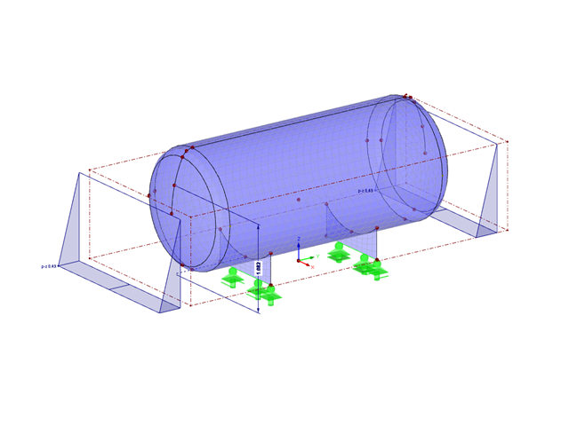
A fluid with a constant density in a homogeneous gravity field exerts a hydrostatic pressure on its comprehensive container wall according to Pascal's law.
RF‑/FOUNDATION Pro allows you to check the allowable eccentricity of the soil pressure resultants. According to DIN EN p;1997‑1/NA, this design is to be carried out with characteristic or representative loads.
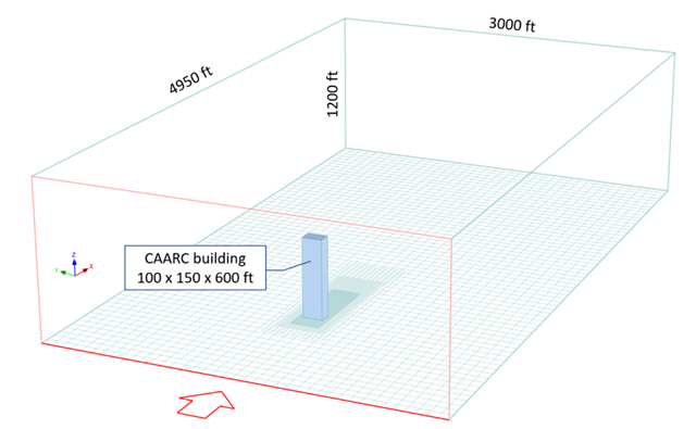
The following study compares the wind pressure on a tall building obtained by RWIND Simulation with the results published by Dagnew et al. at the 11th Americas Conference on Wind Engineering in June, 2009. In this paper, the Commonwealth Advisory Aeronautical Council (CAARC) building is used as a model, and the results of several different numerical methods are compared with experimental data obtained from wind tunnels.
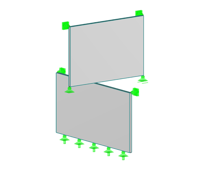
This article describes how to determine the contact force between two objects behaving like walls that are diagonally inclined at a certain angle on top of each other. Define a nodal release to determine this contact force. Since a nodal release requires certain conditions, this article shows two examples.
The definition of the non-linear contact problem plays an important role for more detailed investigations of shear/hole bearing connections or their immediate environment. This article uses a solid model to search for comparable and simplified surface models.
From time to time, two intersecting beams overlap at a short distance. Such a structure raises the question, with regard to the modeling, of how it is possible to consider a contact with force transmission under compression between the two beams, while the contact under tension (for example, in case of a lifting top beam) should fail.
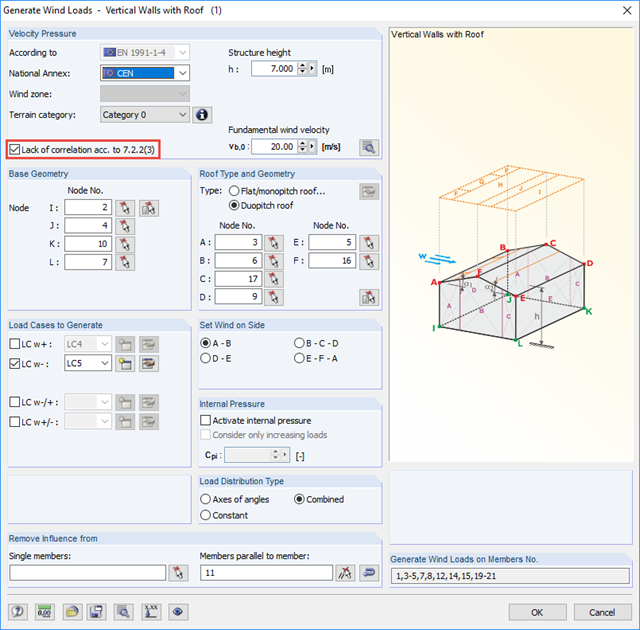
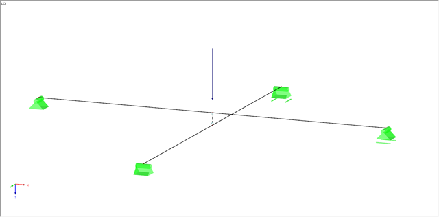
If the wind load for buildings or structures is to be determined by the simultaneous assumption of aerodynamic pressure and suction coefficients on the windward and leeward sides of the building, the correlation of the wind pressure on zones D and E of the wall surfaces may be taken into account.
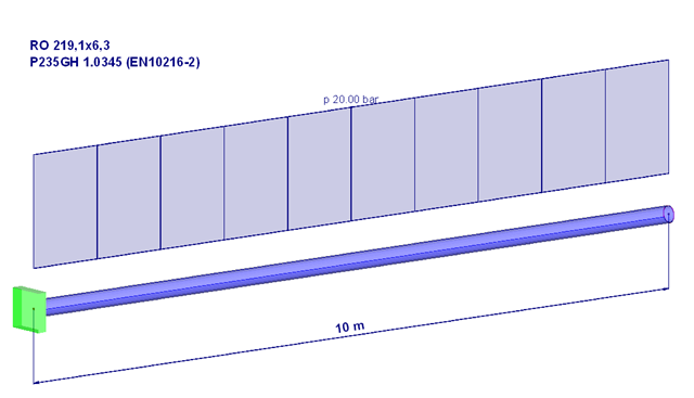
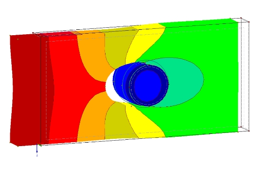
Piping systems are exposed to a variety of loads. One of the most decisive is internal pressure. This article will, therefore, deal with the stresses and deformations resulting from a pure internal compression load in the pipe wall or for the pipe.

Cable and tensile membrane structures are regarded as very slender and aesthetic building structures. The partly very complex double-curved shapes can be found using suitable form-finding algorithms. One possible solution is to search for the form via the equilibrium between the surface stress (provided prestress and an additional load such as self-weight, pressure, and so on) and the given boundary conditions.

Wind is the only climatic load acting on every type of structure in every country in the world, unlike snow. The wind speed depends on the geographic location of the building. Currently, this is one of the main reasons for the necessity of regional division (wind zone) and consideration of the altitude stipulated within the official standards; the variation of the dynamic pressures according to the height above the ground for a "normal" site deprived of masking effect should be taken into account as well.
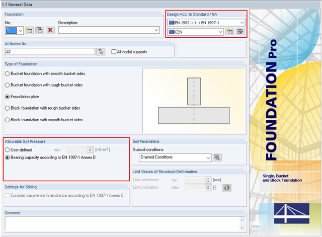
In addition to the reinforced concrete design according to EN 1992‑1‑1, RF-/FOUNDATION Pro allows you to perform geotechnical designs according to EN 1997‑1. In RF-/FOUNDATION Pro, the design of the allowable soil pressure is performed as a ground failure resistance design. If you select CEN as National Annex, you have two options for defining the ground failure resistance. First, you can directly specify the allowable characteristic value of the soil pressure σRk. Second, there is also the option to analytically determine the bearing capacity according to [1], Annex D.
![Time-Dependent Settlement Components [2]](/en/webimage/009673/2419908/01-en-png-png.png?mw=640&hash=5e657e3feb5c1bb6d21727468dd85d91e1c9f29f)
For the serviceability limit state design according to Section 6.6 of Eurocode EN 1997‑1, settlement has to be calculated for spread foundations. RF-/FOUNDATION Pro allows you to perform the settlement calculation for a single foundation. For this, you can chose between an elastic and a solid foundation. By defining a soil profile, it is possible to consider several soil layers under the foundation base. The results of the settlement, foundation tilting, and vertical soil contact stress distribution are displayed graphically and in tables to provide a quick and clear overview of the calculation performed. In addition to the design of the foundation settlement in RF-/FOUNDATION Pro, the structural analysis determines the representative spring constants for the support and can be exported to the structural model of RFEM or RSTAB.

As in RFEM, load combinations can be generated automatically in RF‑PIPING. This feature is activated by default and creates the recommended load and result combinations for piping design. It is necessary to assign the relevant action category to load cases in order to generate the correct combinations. To do this, new action categories have been implemented specifically for loads on piping.
Pressure temperature conditions are generated as the sets of the first (second, third, and so on) load case of the "Pressure" category and the first (second, third, and so on) load case of the "Temperature" category. The default setting can be reviewed or adjusted in the "Grouping of Thermal and Internal Pressure Load Cases for Operating Combinations" dialog box. You can access this dialog box by clicking the corresponding button in the "Piping Load Combinations" tab of the "Load Cases and Combinations" dialog box. This dialog box is automatically offered to check your entries in the case of any change of the load case from the "Pressure" or "Temperature" category.
Pressure temperature conditions are generated as the sets of the first (second, third, and so on) load case of the "Pressure" category and the first (second, third, and so on) load case of the "Temperature" category. The default setting can be reviewed or adjusted in the "Grouping of Thermal and Internal Pressure Load Cases for Operating Combinations" dialog box. You can access this dialog box by clicking the corresponding button in the "Piping Load Combinations" tab of the "Load Cases and Combinations" dialog box. This dialog box is automatically offered to check your entries in the case of any change of the load case from the "Pressure" or "Temperature" category.
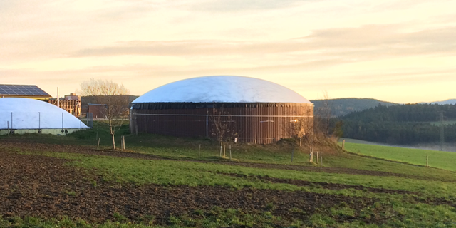
Due to the structural efficiency and economic benefits, dome-shaped roofs are frequently used for storehouses or stadiums. Even if the dome has the corresponding geometrical shape, it is not easy to estimate wind loads due to the Reynolds number effect. The external pressure coefficients (cpe) depend on the Reynolds numbers and on the slenderness of the structure. EN 1991‑1‑4 [1] can help you to estimate the wind loads on a dome. Based on this, the following article explains how to define a wind load in RFEM. Wind loads of the structure shown in Image 01 can be divided as follows: Wind Load on Wall, Wind Load on Dome.
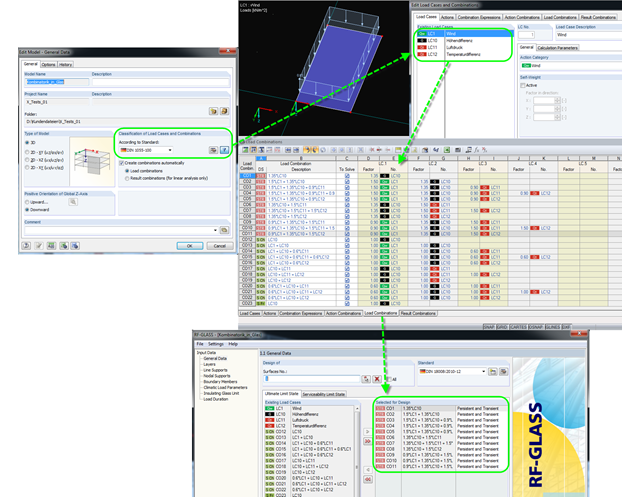
For the superposition or combination of loads, the German standard DIN 18008 refers to DIN 1055‑100. This also applies for the individual parameters of climatic loads to be transferred. In this case, it is possible to summarize the temperature change and meteorological pressure change in a single load and to define the local altitude change as a permanent load.
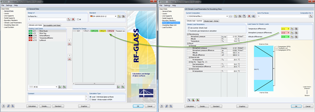
A new feature allows you to assign climatic loads to load cases when designing panes of insulating glass. Climatic loads are included in three categories here: temperature difference, atmospheric pressure difference, and altitude difference.
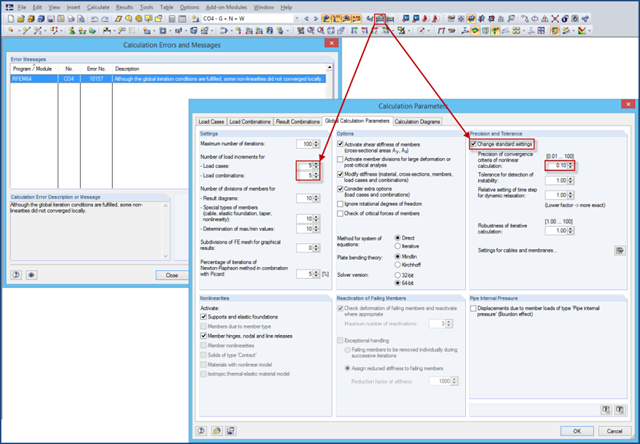
If nonlinearities are used in a model (for example, contact solids), an error message may appear at the end of the calculation due to the locally unfulfilled convergence criteria. The reason for this is that the convergence of the global iteration conditions governs in the calculation.
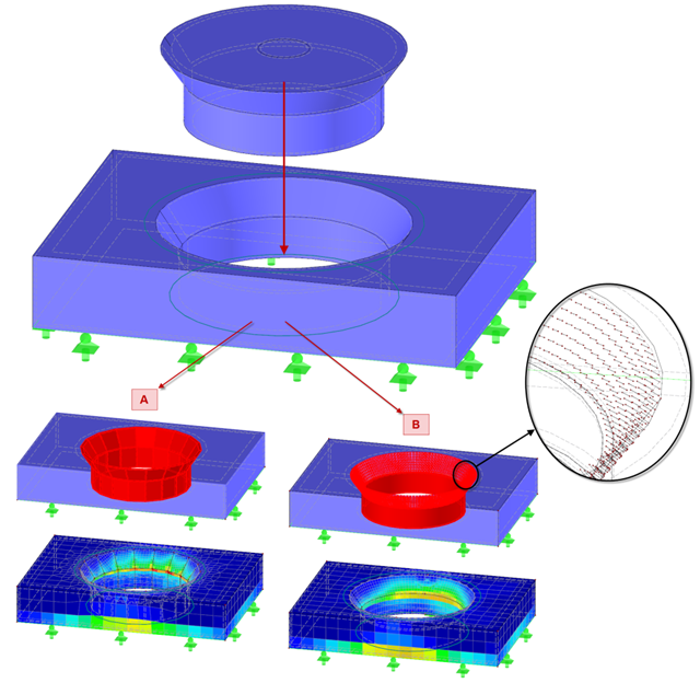
Contact solids can be created between two flat surfaces or between two cylindrical shells. However, if the area of the contact problem is a little more complicated, it is necessary either to simplify the system so that the requirements of a contact solid can be met, or go back to the "old" modeling style using a rod model.
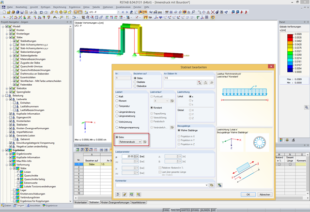
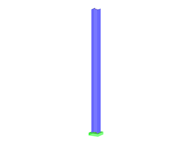
In addition to bending, torsional, longitudinal, and strain loads, you can define and analyze the internal pressure of members with circular hollow cross‑sections in RFEM and RSTAB. The following perimeter and axial stresses resulting from the internal pressure load are analyzed using Barlow's formula and transferred to design modules in order to superimpose the remaining stresses due to internal forces.